Why do inductors overheat in electronic power supply circuits?
An overheating inductor can turn a routine power supply repair into repeated equipment downtime. A replacement may run normally on the bench, then overheat again inside a sealed control cabinet. For after-sales teams maintaining industrial controllers, smart-building systems, railway auxiliary equipment, or heavy-machinery electronics, the challenge is not simply finding the hot component. It is understanding why that component is absorbing more energy than it can release.
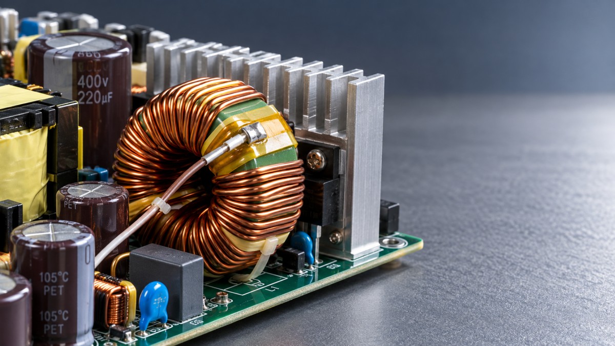
Among electronics components, inductors deserve particular attention because excessive heat can result from winding resistance, magnetic core losses, saturation, abnormal current, or poor cooling. The inductor may be defective—but it may also be revealing a fault elsewhere. Reliable troubleshooting separates those possibilities before another part is fitted.
Is the inductor overheating, or just operating warm?
Inductors normally dissipate power, so a warm surface does not automatically indicate failure. The useful question is whether the component remains within its specified temperature limits under the actual operating conditions.
Check the manufacturer’s maximum component temperature, rated temperature rise, and current-rating conditions. Some current ratings assume a particular ambient temperature and PCB arrangement. Others represent a specified inductance drop rather than a thermal limit. These figures are not interchangeable.
A practical starting relationship is:
Component temperature ≈ local ambient temperature + temperature rise from operation.
“Local ambient” means the air around the inductor—not the temperature outside the cabinet. A nearby heatsink, blocked filter, or stopped fan can make those environments very different. Also, the visible surface temperature may be lower than the hottest point inside the winding.
Measure with a suitable thermocouple or thermal camera and record load, input voltage, airflow, and elapsed operating time. Thermal-camera readings depend on surface emissivity; shiny terminations can be misleading. Do not use a finger-touch test as a temperature measurement or safety check.
The main reasons inductors generate excessive heat
Winding losses increase with RMS current
The winding has electrical resistance. Its basic copper loss is approximately:
Pcopper = IRMS2 × Rwinding
This square relationship explains why a modest increase in current can create a noticeably larger temperature rise. Copper resistance also increases as the winding gets hotter, adding further loss.
Possible triggers include an overloaded output, a partially shorted downstream circuit, or excessive ripple current. A damaged solder joint or termination can produce localized heating near a pad, which may look like an internal inductor problem.
At switching frequencies, DC resistance alone does not describe all winding losses. Skin and proximity effects increase effective AC resistance. An inductor with acceptable DC resistance may still run too hot when used at an unsuitable frequency or with substantial current ripple.
Core saturation causes current to climb rapidly
An inductor stores energy in its magnetic field. As its core approaches saturation, effective inductance falls. With less inductance, current rises faster during the switching interval, increasing losses and potentially overstressing the switching transistor.
The critical comparison is between peak inductor current and the saturation characteristics at the operating temperature. Average output current alone is insufficient.
For an ideal buck converter in continuous conduction:
Ipeak ≈ Iout + ΔIL/2
Here, ΔIL is peak-to-peak inductor ripple current. Startup, load steps, and fault recovery can produce peaks above the steady-state value. In boost and other converter topologies, inductor current does not simply equal output current; use the correct topology-specific calculation.
Saturation is especially likely after an unsuitable replacement, during input undervoltage, or when current limiting is not working correctly. Check how the manufacturer defines saturation current: it usually corresponds to a stated inductance reduction, not an abrupt universal failure threshold.
Core losses rise under unsuitable switching conditions
Repeated magnetization dissipates energy inside the core. Core loss depends on material, frequency, flux swing, temperature, and waveform. A part selected for one switching frequency may not perform well at another, even when its nominal inductance matches.
Unexpected frequency changes, excessive applied volt-seconds, or a replacement with different core material can therefore increase heating. A normal DC-resistance reading does not rule out excessive core loss.
The surrounding circuit may be creating the problem
A hot inductor can be the messenger rather than the root cause. Degraded output capacitors, unstable feedback, incorrect gate drive, or a failing rectifier can alter converter operation and increase losses. However, output-voltage ripple alone does not prove excessive inductor ripple; it also depends on capacitance and capacitor ESR.
Mechanical and environmental changes matter too. Dust-loaded filters, failed fans, missing thermal interfaces, and cabinet modifications can push a previously acceptable design beyond its thermal limits. This is common in infrastructure equipment exposed to seasonal heat, contamination, or continuous-duty operation.
A diagnostic sequence that avoids unnecessary replacement
Begin with the equipment isolated and follow the applicable service procedure. Mains-powered supplies and high-voltage DC systems may retain dangerous charge after disconnection. Verify discharge before handling. Energized measurements should be performed only by qualified personnel with appropriately rated instruments.
- Reproduce the complaint. Record whether heating occurs at idle, full load, startup, low input voltage, or only after the enclosure is closed. A bench test without the actual load may miss the fault.
- Inspect before powering. Look for cracked cores, darkened winding insulation, loose mounting, damaged solder joints, contamination, and obstructed airflow. Confirm the installed part number against the approved bill of materials.
- Measure input, output, and load. Check whether the supply is operating within specification. Compare with a known-good unit under equivalent conditions when available.
- Map temperatures. Monitor the inductor, switching devices, rectifiers, capacitors, and nearby air. Observe whether temperature stabilizes or continues climbing toward a limit.
- Examine switching behavior. Measure frequency, inductor current, and relevant voltage waveforms. Look for abnormal ripple, erratic switching, current-limit operation, and unusually steep current rise near the end of a switching pulse.
- Change one condition at a time. Reduce load or restore specified airflow, then repeat the measurements. Controlled comparisons are more useful than replacing several components simultaneously.
Use an appropriately rated current probe where possible. Differential voltage probes may be required for floating switching nodes. Never connect an earth-referenced oscilloscope ground clip to a live switching node; this can create a destructive short and an electric-shock hazard.
When checking inductance or resistance, isolate the component as necessary to avoid misleading parallel paths. A handheld LCR meter typically measures with a small test signal and little or no DC bias. A normal reading therefore does not prove that the inductor retains adequate inductance at its working current.
What the observed heating pattern can tell you
These patterns guide investigation; they are not standalone diagnoses. Audible buzzing, for example, may come from normal burst-mode operation rather than a failing core. Likewise, discoloration indicates thermal exposure but does not identify its original cause.
Choosing the corrective action—not just a cooler-looking part
If current exceeds the intended operating range, investigate the load and control circuit before changing the inductor. A larger component may hide the symptom while leaving a failing motor driver, damaged capacitor, or incorrect current limit unresolved.
Where replacement is necessary, matching only inductance and package size is insufficient. Review:
- Inductance under DC bias: the value must remain suitable at actual working current.
- Saturation current: allow appropriate margin for peaks, transients, and operating temperature.
- Thermal current rating: assess the stated temperature rise and test conditions.
- DC resistance and AC losses: both influence heating in switching applications.
- Core material and frequency suitability: equivalent-looking parts may have different loss behavior.
- Construction and environmental ratings: shielding, insulation, vibration resistance, and temperature range must suit the equipment.
Increasing inductance is not an automatic cure. It can reduce ripple in some circuits but may affect transient response, compensation, current sensing, and protection behavior. Lower inductance can increase ripple and peak current. Changes outside the approved specification require engineering review.
Cooling corrections should restore the intended thermal design: replace failed fans, clean filters, recover clearances, and repair specified thermal interfaces. Adding an improvised heatsink can introduce electrical-clearance or mechanical problems. In sealed outdoor equipment, improving internal heat conduction may be more appropriate than introducing ventilation that compromises environmental protection.
Verify the repair under conditions that caused the failure
A successful repair is not simply an inductor that feels cooler during a short bench run. Test across the specified operating range, including relevant input-voltage extremes, representative load changes, startup, and expected enclosure conditions. Confirm that peak current remains acceptable and temperatures stabilize below applicable limits.
Keep a service record containing the replacement part number, measured load, local ambient temperature, stabilized component temperature, and relevant waveforms. For fleets of smart-city controllers, building automation panels, or heavy-equipment power modules, consistent records can reveal recurring enclosure, sourcing, or loading problems that isolated repairs miss.
The central principle is simple: an overheating inductor is evidence of excessive electrical loss, inadequate heat removal, or both. Measuring current, checking magnetic limits, and evaluating the real thermal environment turns that evidence into a defensible repair—rather than another replacement followed by another callout.
Questions about this sector or your project? Contact Sector Deep Dive for expert insights.
We respect your privacy. Your information is strictly confidential.
Get weekly intelligence in your inbox.
No noise. No sponsored content. Pure intelligence.
News Recommendations
 Oct 25, 2026How to prioritize renewals in global infrastructure asset managementHow to prioritize renewals in global infrastructure asset management
 Oct 20, 2026Why do inductors overheat in electronic power supply circuits?Why do inductors overheat in electronic power supply circuits?
 Oct 12, 2026How heavy equipment failure analysis traces recurring pump failuresHow heavy equipment failure analysis traces recurring pump failures
 Oct 12, 2026Using heavy machinery failure analysis to identify fatigue cracksUsing heavy machinery failure analysis to identify fatigue cracks
 Oct 08, 2026Which automated equipment monitoring sensors suit harsh sitesWhich automated equipment monitoring sensors suit harsh sites
 Oct 08, 2026How automation lifecycle planning prevents costly retrofit gapsHow automation lifecycle planning prevents costly retrofit gaps
 Sep 14, 2026When Should You Update Supplier Capability Data? Triggers, Frequency & Audit RequirementsWhen Should You Update Supplier Capability Data? Triggers, Frequency & Audit Requirements
 Sep 14, 2026How should smart devices be maintained in harsh outdoor conditions?How should smart devices be maintained in harsh outdoor conditions?
 Aug 25, 2026Common Wine Tank Cleaning and Corrosion Issues in Fermentation SystemsCommon Wine Tank Cleaning and Corrosion Issues in Fermentation Systems
 Aug 08, 2026How Maintenance Technologies for Railways Reduce Downtime and Track Failure RiskHow Maintenance Technologies for Railways Reduce Downtime and Track Failure Risk
 Jul 14, 2026Predictive Heavy Machinery Analysis: 5 Signals of Early FailurePredictive Heavy Machinery Analysis: 5 Signals of Early Failure
 Jul 10, 2026When Industrial Technology Services Reduce Downtime MostWhen Industrial Technology Services Reduce Downtime Most
 Jul 10, 2026How to Compare Automation Equipment Sensors for Uptime and AccuracyHow to Compare Automation Equipment Sensors for Uptime and Accuracy
 Jul 09, 2026Rail Maintenance Asset Monitoring: Key Failure SignalsRail Maintenance Asset Monitoring: Key Failure Signals
![]() Jul 07, 2026Automation Equipment Supplier Checklist for Stable After-Sales SupportAutomation Equipment Supplier Checklist for Stable After-Sales Support
 Jul 02, 2026Railway Maintenance Systems Equipment: Key Features That Reduce DowntimeRailway Maintenance Systems Equipment: Key Features That Reduce Downtime
 Jun 29, 2026Railway Maintenance Systems: Key Features That Reduce DowntimeRailway Maintenance Systems: Key Features That Reduce Downtime
 Jun 28, 2026Industrial Accessories Checklist for Reducing DowntimeIndustrial Accessories Checklist for Reducing Downtime
 Jun 27, 2026Special Purpose Vehicles and Equipment: Key Maintenance ChecksSpecial Purpose Vehicles and Equipment: Key Maintenance Checks
 Jun 20, 2026Maintenance Technologies for Railways That Reduce Downtime and Repair RiskMaintenance Technologies for Railways That Reduce Downtime and Repair Risk
 Jun 16, 2026Maintenance Technologies for Smart Buildings That Reduce DowntimeMaintenance Technologies for Smart Buildings That Reduce Downtime
 Jun 10, 2026Railway Maintenance Costs: Key Factors That Impact Lifecycle BudgetsRailway Maintenance Costs: Key Factors That Impact Lifecycle Budgets
 Jun 07, 2026Heavy Machinery Maintenance Costs: What Impacts Downtime Most in 2026Heavy Machinery Maintenance Costs: What Impacts Downtime Most in 2026
 Jun 06, 2026Maintenance Technologies for Heavy Equipment That Reduce DowntimeMaintenance Technologies for Heavy Equipment That Reduce Downtime
![]() Jun 04, 20262026 Maintenance Technologies: Which Upgrades Cut Downtime Fastest?2026 Maintenance Technologies: Which Upgrades Cut Downtime Fastest?
 Jun 03, 2026Maintenance Technologies for Heavy Equipment That Cut Downtime in 2026Maintenance Technologies for Heavy Equipment That Cut Downtime in 2026
 Jun 02, 2026Maintenance Technologies That Cut Fleet DowntimeMaintenance Technologies That Cut Fleet Downtime