Which automated equipment monitoring sensors suit harsh sites
For harsh sites, the most suitable automated equipment monitoring sensors are usually not the ones with the longest feature list. They are the sensors that keep producing trustworthy data after exposure to dust, washdown, shock, temperature swings, electrical noise, and intermittent communications.
A practical starting point is to match the sensing method to the failure mode, then assess whether the complete installation can survive the environment. A vibration sensor on a crusher bearing, a pressure sensor on a hydraulic circuit, a temperature sensor on a traction motor, and a position sensor on a crane boom solve different problems. None should be selected solely because its datasheet shows a high enclosure rating.
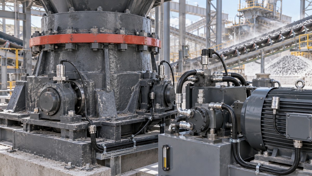
For infrastructure, mining, railway, construction, and special-purpose vehicle fleets, a robust monitoring system commonly combines rugged vibration sensing, temperature measurement, pressure monitoring, fluid-condition sensing, electrical monitoring, and location or position sensing. The right mix depends on the asset, the consequence of failure, access for maintenance, and the quality of the available power and network connection.
Start with the asset and the failure you need to detect
Sensor selection becomes clearer when the evaluation begins with an operational question: What developing condition should the system reveal early enough to support action? “Monitor the machine” is too broad. A useful monitoring point has a known failure pathway, a measurable change, and a decision that follows from the data.
Consider a few typical examples. Rotating equipment such as pumps, fans, conveyors, gearboxes, and rail-side drives often develops bearing, imbalance, looseness, or gear-mesh issues. Vibration and temperature measurements can be useful, but they serve different purposes. Vibration is better suited to identifying mechanical changes before surface temperature rises significantly; temperature is often a simpler indicator of overload, poor lubrication, or an already advanced fault.
Hydraulic equipment creates another monitoring pattern. Excavators, lifting equipment, concrete machinery, and mobile service vehicles may need pressure, temperature, contamination, and cylinder-position data. Pressure alone can show whether a circuit is operating in its expected range, but it cannot always explain whether the root cause is a worn pump, blocked filter, internal leakage, an overloaded actuator, or a control-valve problem. Combining a small number of well-placed signals is usually more useful than installing many unrelated sensors.
Electrical assets need the same discipline. Current, voltage, insulation condition, winding temperature, enclosure humidity, and motor vibration can each be relevant. The selection should follow the likely fault mechanism and the available access points. Adding a sensor because it is easy to attach can create a data stream without creating a maintenance decision.
Choose the sensor family by what it can reveal
Vibration sensors deserve closer scrutiny because they are frequently specified for condition monitoring and frequently installed poorly. A sensor mounted on a thin guard, painted surface, loose bracket, or distant structural member may measure the behavior of the mounting arrangement more than the bearing or gearbox. The sensor element may be capable of good measurement, yet the installed signal may be unsuitable for diagnosis.
For fixed industrial equipment, a rigid mounting point near the fault source is often preferable. For mobile equipment, installation also needs to accommodate chassis flex, repetitive shock, mud, and cable movement. Where a permanent cable route is likely to be damaged, a wireless sensor may reduce installation risk, but it introduces battery, radio-path, and data-transmission questions that must be treated as part of the design.
Pressure sensing also needs a system-level view. A sensor should be selected for the working medium and the pressure behavior of the circuit, including transient events. A pressure port that is exposed to pulsation, vibration, or mechanical loading can shorten service life even when the nominal pressure range appears appropriate. Remote mounting, suitable adapters, or protective routing may be more valuable than choosing a more sophisticated transmitter.
Environmental protection is more than an IP rating
An enclosure rating is useful, but it answers only part of the question. It indicates resistance to ingress under defined conditions; it does not prove that the sensor will remain reliable when subjected to abrasive dust, chemical washdown, sustained vibration, ultraviolet exposure, salt-laden air, pressure pulses, or repeated thermal cycling.
Evaluate the complete sensor assembly: housing, sensing face, connector, cable, gland, mounting hardware, and exposed interfaces. A rugged metal sensor body can still fail because water enters through a poorly terminated field connector. Likewise, a sealed sensor can produce unstable readings when its cable insulation hardens, cracks, or is cut by abrasion.
Dust-heavy locations such as quarries, mines, aggregate plants, and construction sites need attention to abrasion and buildup. Fine dust can obstruct optical or ultrasonic sensors, cover heat-dissipation surfaces, and work into connector threads. In these locations, non-contact technologies should be chosen only when their sensing surface can remain clear or be protected by the installation geometry. Inductive proximity sensors often tolerate contamination better than optical approaches for simple metallic-target detection, but they still require correct sensing distance and target alignment.
Wet and corrosive locations require material compatibility, not only sealing. Coastal assets, tunnels, wastewater facilities, road-treatment equipment, and chemical processing zones can expose sensor housings and connectors to corrosive agents. Review the materials that contact the process fluid as well as the materials exposed externally. The right housing for a dry indoor cabinet may be unsuitable on an exposed vehicle or next to a washdown point.
Temperature evaluation must distinguish ambient temperature from the temperature at the mounting point. A sensor on a gearbox casing, a hydraulic manifold, a brake assembly, or near an engine compartment may experience heat transfer that is much greater than the surrounding air temperature suggests. Cold environments add a different risk: cable stiffness, battery performance, condensation during warm-up, and changes in sensor response. The selected operating range should reflect the actual installed location rather than the general site climate.
Vibration, shock, and mounting can invalidate an otherwise good choice
Heavy equipment and rail assets often expose sensors to two different mechanical stresses. Continuous vibration can affect measurement stability and fatigue life, while short-duration shock can damage electronics, connectors, or mounting threads. A sensor intended to measure machine vibration must also survive the vibration and shock imposed by the host asset. These are related, but they are not the same specification.
Check whether the supplier describes resistance to mechanical shock and continuous vibration separately. Then inspect the mounting concept. Threaded mounting, stud mounting, magnetic mounting, adhesive pads, brackets, and clamp arrangements have different reliability profiles. Magnetic mounting may be convenient for surveys or temporary validation, but it is usually a weak choice for a long-term installation exposed to high vibration, impact, theft risk, or repeated washdown.
Mounting orientation matters for interpretation. A triaxial vibration sensor can capture changes across multiple axes, which is useful where vibration direction is uncertain or structural motion is complex. A single-axis device can be adequate when the measurement direction and failure mechanism are established. More axes are not automatically better if the monitoring platform cannot process or interpret the resulting data.
Communications should fit the site, not the product brochure
Hardwired sensors remain a strong option where cable routes are protected, power is available, and continuous data is necessary. They avoid battery replacement and can support high-frequency measurements, making them appropriate for applications where detailed waveform or spectral information matters. Their main weakness is installation cost and vulnerability at cable runs, especially on moving machines or large distributed sites.
Wireless automated equipment monitoring sensors are useful when retrofitting isolated assets, temporary machinery, rotating structures, or locations where cabling would be disruptive. Their suitability depends on more than stated radio range. Steel structures, tunnels, stockpiles, vehicle movement, underground workings, electromagnetic interference, and equipment layout can all change signal quality. A short site survey around the actual mounting locations is more informative than a nominal range figure.
Battery-powered devices also need a reporting strategy. Frequent raw-data transmission consumes more energy than periodic health summaries or exception-based alerts. A sensor that sends fewer, decision-ready measurements may be more sustainable for remote assets than one designed to transmit every possible reading. Conversely, reducing reporting too aggressively can hide the progression of a fast-developing fault. Data frequency should follow fault criticality and expected rate of change.
For fleet equipment, gateway placement deserves the same attention as sensor selection. A reliable sensor connected to an unreliable gateway path is not a reliable monitoring system. Plan how data moves from the asset to a local controller, edge gateway, maintenance platform, or enterprise system, and define what happens when that path is unavailable. Local buffering, alarm behavior, and recovery after reconnection should be clear before deployment.
Do not confuse data collection with condition monitoring
Condition monitoring becomes operationally valuable only when a reading can be compared with a meaningful baseline, operating state, or threshold. A hydraulic temperature reading means something different during cold start, full-load work, idle time, and hot ambient conditions. Motor current changes with load. Vibration values can shift when speed, material flow, or mounting stiffness changes.
That is why sensor selection should include the contextual inputs required to interpret the data. In some cases, one additional signal such as shaft speed, machine operating state, load, or ambient temperature prevents a large number of false alerts. It may be better to monitor fewer assets with usable context than to deploy a broad sensor network that creates an unmanageable alarm queue.
Thresholds should not be treated as permanent from the first day. A practical rollout establishes normal behavior across representative operating conditions, then refines alarm rules as the team learns which variations are normal and which warrant inspection. This does not require a complex analytics program at every site. It requires clear ownership: who reviews the alert, what inspection follows, and how the outcome is recorded.
A procurement checklist that exposes weak proposals
When comparing sensor packages, ask suppliers and internal stakeholders to answer the same deployment questions:
- Which failure mode does each sensor address, and what maintenance action can follow from its alert?
- What will the sensor experience at its exact mounting point: dust, fluid, washdown, impact, heat, vibration, UV exposure, or corrosion?
- Does the proposed mounting method preserve measurement quality and allow practical inspection or replacement?
- How are connectors, cables, and gateways protected from abrasion, moisture, and accidental damage?
- Is the system designed for continuous data, periodic readings, event reporting, or local alarms, and does that match the risk?
- What data remains available during a network outage, and how is it recovered?
- Can maintenance teams identify a failed sensor, a communication problem, and a genuine asset fault as separate conditions?
- Will the output integrate with the maintenance workflow, or will it require manual interpretation in a separate dashboard?
One common mistake is specifying a rugged sensor and then accepting a fragile deployment arrangement. Another is purchasing broad monitoring capability without defining which assets are critical enough to justify it. The strongest proposals connect the monitored condition to downtime risk, safety exposure, maintenance access, and the time available to intervene.
Where a pilot delivers the most value
A focused pilot is especially useful when the site includes variable loads, unusual contamination, difficult radio propagation, or equipment from different generations. Select a small group of representative assets rather than only the newest or easiest machines. Include at least one location that reflects the harshest expected environmental and communication conditions.
The pilot should test installation practicality as well as sensor readings. Inspect cable routing after normal operation, confirm that connectors remain accessible, observe whether vibration measurements remain repeatable, and verify that alerts reach the people responsible for action. A monitoring system that produces technically correct information but cannot be serviced or acted upon will not remain reliable in the field.
For the infrastructure and urban-tech sectors covered by GIUT, the most defensible choice is rarely a single “best” sensor. It is a monitoring architecture built around the equipment’s failure modes and the realities of the site. Choose rugged vibration monitoring where mechanical condition must be detected early, pressure and fluid sensing where hydraulic performance drives availability, electrical and temperature sensing where load or thermal stress matters, and resilient communications that can tolerate the operating environment. Then validate the installation as rigorously as the sensor itself.
Questions about this sector or your project? Contact Sector Deep Dive for expert insights.
We respect your privacy. Your information is strictly confidential.
Get weekly intelligence in your inbox.
No noise. No sponsored content. Pure intelligence.
News Recommendations
 Oct 25, 2026How to prioritize renewals in global infrastructure asset managementHow to prioritize renewals in global infrastructure asset management
 Oct 20, 2026Why do inductors overheat in electronic power supply circuits?Why do inductors overheat in electronic power supply circuits?
 Oct 12, 2026How heavy equipment failure analysis traces recurring pump failuresHow heavy equipment failure analysis traces recurring pump failures
 Oct 12, 2026Using heavy machinery failure analysis to identify fatigue cracksUsing heavy machinery failure analysis to identify fatigue cracks
 Oct 08, 2026Which automated equipment monitoring sensors suit harsh sitesWhich automated equipment monitoring sensors suit harsh sites
 Oct 08, 2026How automation lifecycle planning prevents costly retrofit gapsHow automation lifecycle planning prevents costly retrofit gaps
 Sep 14, 2026When Should You Update Supplier Capability Data? Triggers, Frequency & Audit RequirementsWhen Should You Update Supplier Capability Data? Triggers, Frequency & Audit Requirements
 Sep 14, 2026How should smart devices be maintained in harsh outdoor conditions?How should smart devices be maintained in harsh outdoor conditions?
 Aug 25, 2026Common Wine Tank Cleaning and Corrosion Issues in Fermentation SystemsCommon Wine Tank Cleaning and Corrosion Issues in Fermentation Systems
 Aug 08, 2026How Maintenance Technologies for Railways Reduce Downtime and Track Failure RiskHow Maintenance Technologies for Railways Reduce Downtime and Track Failure Risk
 Jul 14, 2026Predictive Heavy Machinery Analysis: 5 Signals of Early FailurePredictive Heavy Machinery Analysis: 5 Signals of Early Failure
 Jul 10, 2026When Industrial Technology Services Reduce Downtime MostWhen Industrial Technology Services Reduce Downtime Most
 Jul 10, 2026How to Compare Automation Equipment Sensors for Uptime and AccuracyHow to Compare Automation Equipment Sensors for Uptime and Accuracy
 Jul 09, 2026Rail Maintenance Asset Monitoring: Key Failure SignalsRail Maintenance Asset Monitoring: Key Failure Signals
![]() Jul 07, 2026Automation Equipment Supplier Checklist for Stable After-Sales SupportAutomation Equipment Supplier Checklist for Stable After-Sales Support
 Jul 02, 2026Railway Maintenance Systems Equipment: Key Features That Reduce DowntimeRailway Maintenance Systems Equipment: Key Features That Reduce Downtime
 Jun 29, 2026Railway Maintenance Systems: Key Features That Reduce DowntimeRailway Maintenance Systems: Key Features That Reduce Downtime
 Jun 28, 2026Industrial Accessories Checklist for Reducing DowntimeIndustrial Accessories Checklist for Reducing Downtime
 Jun 27, 2026Special Purpose Vehicles and Equipment: Key Maintenance ChecksSpecial Purpose Vehicles and Equipment: Key Maintenance Checks
 Jun 20, 2026Maintenance Technologies for Railways That Reduce Downtime and Repair RiskMaintenance Technologies for Railways That Reduce Downtime and Repair Risk
 Jun 16, 2026Maintenance Technologies for Smart Buildings That Reduce DowntimeMaintenance Technologies for Smart Buildings That Reduce Downtime
 Jun 10, 2026Railway Maintenance Costs: Key Factors That Impact Lifecycle BudgetsRailway Maintenance Costs: Key Factors That Impact Lifecycle Budgets
 Jun 07, 2026Heavy Machinery Maintenance Costs: What Impacts Downtime Most in 2026Heavy Machinery Maintenance Costs: What Impacts Downtime Most in 2026
 Jun 06, 2026Maintenance Technologies for Heavy Equipment That Reduce DowntimeMaintenance Technologies for Heavy Equipment That Reduce Downtime
![]() Jun 04, 20262026 Maintenance Technologies: Which Upgrades Cut Downtime Fastest?2026 Maintenance Technologies: Which Upgrades Cut Downtime Fastest?
 Jun 03, 2026Maintenance Technologies for Heavy Equipment That Cut Downtime in 2026Maintenance Technologies for Heavy Equipment That Cut Downtime in 2026
 Jun 02, 2026Maintenance Technologies That Cut Fleet DowntimeMaintenance Technologies That Cut Fleet Downtime