How to check joint fit in prefabricated construction quality assurance
A poorly fitted joint can compromise load transfer, weather resistance, and installation safety long before defects become visible. In construction quality assurance prefabrication workflows, checking joint fit means more than confirming that components line up. Inspectors must verify dimensions, alignment, bearing contact, and connection clearances against approved drawings and project-specific tolerances.
The difficult decisions often happen under pressure: a module is waiting on the crane, a precast panel appears slightly out of position, or a bolt will not pass through its hole. A reliable inspection process gives quality control and safety teams a defensible answer to one question: can this assembly proceed safely, or must installation stop for review?
Define acceptance before checking the joint
“It fits” is not an acceptance criterion. A joint may look tidy while providing insufficient bearing, restricting thermal movement, or leaving too little space for grout. Conversely, a visible gap may be intentional and necessary for installation or service movement.
Before inspection, identify the joint’s function and assemble the applicable requirements:
- Approved fabrication and erection drawings: component dimensions, joint geometry, connection details, and drawing revisions.
- Project specifications: dimensional tolerances, inspection methods, acceptance criteria, and required records.
- Connection and product instructions: requirements for bearings, fasteners, sleeves, grout, gaskets, and sealants.
- Inspection and test plan: inspection responsibilities, sampling requirements, witness points, and hold points.
- Engineered erection procedure: temporary supports, bracing, installation sequence, and conditions for releasing lifting equipment.
Separate fabrication tolerances from erection tolerances and final interface requirements. A component can satisfy its manufacturing tolerance yet fail to fit because deviations in the supporting structure and neighboring components accumulate.
Applicable references depend on the material, jurisdiction, and contract. These may include ACI 117 and relevant PCI guidance for concrete work, EN 13670 for execution of concrete structures, EN 1090-2 for steel execution, or AWS D1.1 for specified structural steel welding work. None should be treated as a universal joint-fit checklist. Confirm the applicable edition, scope, and contractual requirements with the responsible engineer.
Check three different conditions—not just the visible gap
A practical inspection separates joint fit into three questions: is the component in the correct position, does the interface have the required geometry, and can the connection perform as designed?
This distinction matters because one satisfactory measurement cannot prove overall compliance. A panel can be plumb but inadequately seated. A steel splice can accept its bolts while exceeding the permitted fit-up gap. A modular façade joint can have the correct width while its gasket is rolled or interrupted.
A field sequence that prevents misleading measurements
Confirm identity, condition, and safe access
Match component identification to the erection layout and current drawings. Check for transport damage, distorted connection plates, displaced inserts, damaged edges, and debris on mating surfaces. Make sure the receiving structure has been accepted for the next installation stage.
Inspection must not put anyone beneath a suspended load or inside an uncontrolled pinch zone. Temporary support, bracing, exclusion zones, and access arrangements should follow the approved erection plan. Inspectors should not direct improvised adjustments that change the engineered lifting or restraint arrangement.
Establish a trustworthy reference
Use verified survey control rather than assuming adjacent components are correct. Confirm that control points remain undisturbed and that instruments are suitable for the required accuracy.
Record whether measurements were taken while the component was crane-supported, temporarily braced, or in its specified inspection condition. Position can change as load transfers or restraints are adjusted. Temperature and other environmental conditions may also affect long components and narrow movement joints.
Measure position before local fit
Check elevation, line, plumb, and rotation at the locations identified in the inspection plan. Measuring only one corner can miss twist or taper. For repeated modules or long panel runs, monitor cumulative drift against the building grid rather than only checking each unit against its neighbor.
Then inspect the interface. Measure joint width at the specified locations, including along its length where variation is possible. Check bearing dimensions, contact conditions, and connection clearances before finishes, grout, or cover plates hide them.
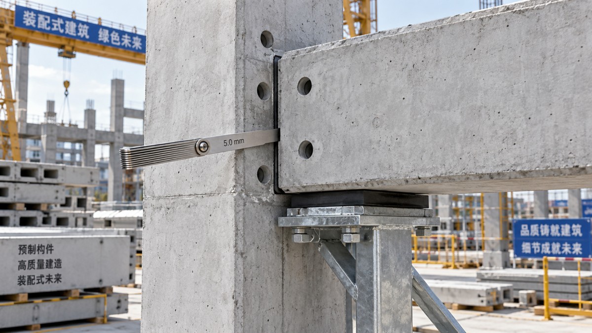
An annotated joint detail is useful here: show the survey datum, gap measurement locations, required bearing zone, and areas that become inaccessible after connection completion. The drawing should distinguish designed clearances from unintended gaps.
Verify connection readiness before release
Confirm that the components can be connected using the specified procedure without unauthorized alteration. After positioning, inspect accessible interfaces again where adjustment could have changed bearing, alignment, or gasket condition.
Release each hold point only through the designated authority. A passed fit-up check does not automatically authorize crane release, removal of temporary bracing, grouting, or concealment; those stages may have separate requirements.
Match the tools to the measurement
A tape measure remains useful for broad dimensions, but it is not enough for every joint. Select instruments according to the acceptance range, accessibility, and geometry being measured.
- Total stations and suitable laser instruments: component location, elevation, plumb, and overall alignment against survey control.
- Calipers, gap gauges, and feeler gauges: accessible local dimensions and gaps, where the contact surfaces allow reliable readings.
- Straightedges and levels: localized steps, alignment, and flatness checks within their practical limits.
- Borescopes and inspection mirrors: visual checks of otherwise difficult-to-see interfaces; these do not independently establish dimensions.
- Laser scanning: complex geometry and cumulative deviation, provided registration, resolution, and measurement uncertainty suit the task.
Check calibration status or verification records as required by the quality system. Keep measurement uncertainty small enough to support the acceptance decision. When a reading approaches a tolerance boundary, confirm it with an appropriate method rather than rounding it into compliance.
Photographs strengthen the record but do not replace measurements. Include an identifiable location and a scale where useful; perspective can make a nonuniform gap look acceptable.
Different prefabricated systems need different fit checks
Precast concrete: bearing and grout space deserve special attention
For bearing joints, verify the specified bearing length and width, bearing-pad location, supporting surface condition, and seating arrangement. Edge damage or an incorrectly positioned pad can reduce the effective support area even when the component’s overall location is correct.
Inspect dowels, projecting reinforcement, sleeves, and pockets for alignment and required engagement. Confirm that grout spaces, inlets, and vents match the approved detail and remain unobstructed. A connection that looks closed externally may contain interference that prevents proper filling.
Do not assume shims can correct every discrepancy. Shim material, position, thickness, and whether it remains permanently must comply with the engineered detail.
Steel assemblies: avoid confusing forced assembly with acceptable fit
Check mating surfaces, plate alignment, hole position, bolt access, and specified fit-up gaps. Bolt insertion alone is not proof of compliance. Tightening should not be used to pull a distorted assembly into position unless the approved connection and erection procedure explicitly permit that action.
For welded joints, verify the fit-up dimensions required by the approved detail and welding procedure, including root opening, alignment, and access where applicable. Final weld inspection is a separate activity; acceptable fit-up does not establish weld quality.
Unapproved hole enlargement, slotting, heating, cutting, or grinding can change connection behavior. Record the discrepancy and obtain the required engineering disposition before alteration.
Volumetric modules and façades: check continuity as well as alignment
Module interfaces combine structural connections with weather, fire, acoustic, and service requirements. Confirm that structural alignment does not obstruct service connections or reduce the space needed for specified interface systems.
For façade joints, assess joint width and depth, sealant backing, substrate condition, and gasket seating against the approved system details. A narrow joint may look neat but lack the movement capacity required in service. Fire-stopping must match the approved system or tested configuration, including its permitted joint dimensions and movement conditions.
Turn a failed fit check into a controlled decision
When a joint falls outside its acceptance criteria, identify the affected assembly and prevent the next activity from concealing or worsening the problem. Follow the project’s nonconformance process and maintain the required temporary stability arrangements.
A useful nonconformance record includes:
- Component and joint identification, location, date, and relevant drawing revision.
- The specified requirement and its source.
- Measured values, measurement locations, method, and instrument identification where required.
- Photographs or marked-up details showing the discrepancy.
- The assembly’s support condition and any associated safety concern.
- The authorized disposition, corrective work, and reinspection result.
Avoid descriptions such as “slightly misaligned.” They leave the engineer without enough information to evaluate load transfer, installation feasibility, or movement allowance.
Possible dispositions include repositioning, an approved repair, replacement, or acceptance through documented engineering assessment. Quality personnel should not independently waive a structural requirement. Once corrective work is complete, reinspect both the original defect and any interfaces affected by the change.
Use digital records to find patterns, not just close reports
GIUT’s focus on connecting physical infrastructure with digital intelligence is particularly relevant to joint inspection. Measurements linked to component identifiers and model locations can reveal recurring problems that isolated paper reports miss.
A BIM-linked inspection record can help distinguish a fabrication issue from a survey-control problem or erection-sequence effect. However, a model comparison is only meaningful when model revisions, coordinate systems, and measurement quality are controlled. Digital alignment is not, by itself, evidence of adequate bearing or a complete concealed connection.
Review trends across production batches, interface types, and installation areas. Repeated near-limit results deserve attention even before failures become frequent. They may indicate that nominal dimensions leave too little practical installation allowance.
The decision to proceed should be traceable
Before releasing a joint to the next stage, confirm that its position, interface geometry, and connection readiness satisfy the applicable requirements. Make sure nonconformities have authorized dispositions, required reinspections are complete, and evidence has been captured before concealment.
The strongest prefabrication quality assurance process is not the one with the most measurements. It is the one that measures the right features at the right time—and gives the inspection team clear authority to pause when fit, stability, or connection performance remains uncertain.
Questions about this sector or your project? Contact Sector Deep Dive for expert insights.
We respect your privacy. Your information is strictly confidential.
Get weekly intelligence in your inbox.
No noise. No sponsored content. Pure intelligence.
News Recommendations
 Oct 12, 2026How to check joint fit in prefabricated construction quality assuranceHow to check joint fit in prefabricated construction quality assurance
 Oct 08, 2026When Prefabricated Solutions Deliver Lower Project Risk Than Site-Built MethodsWhen Prefabricated Solutions Deliver Lower Project Risk Than Site-Built Methods
 Oct 08, 2026What QA Records and Documentation Should Accompany Prefab Assemblies?What QA Records and Documentation Should Accompany Prefab Assemblies?
 Jul 23, 2026How to Evaluate a Prefab Construction Technology Platform for Project DeliveryHow to Evaluate a Prefab Construction Technology Platform for Project Delivery
 Jul 03, 2026Modular Construction Systems: Key Factors for Faster Project DeliveryModular Construction Systems: Key Factors for Faster Project Delivery
![]() Jun 09, 2026Prefabricated Construction Cost: What Drives the Budget?Prefabricated Construction Cost: What Drives the Budget?
 Jun 05, 20262026 Prefabricated Construction Cost: What Drives Budget Overruns?2026 Prefabricated Construction Cost: What Drives Budget Overruns?
![]() Jun 04, 2026Prefabricated Construction Cost in 2026: What Drives Budget Overruns?Prefabricated Construction Cost in 2026: What Drives Budget Overruns?
 May 22, 2026Prefabricated Construction Techniques That Save TimePrefabricated Construction Techniques That Save Time
 May 21, 2026Prefabricated Construction Benefits: Faster Builds, Fewer Site RisksPrefabricated Construction Benefits: Faster Builds, Fewer Site Risks
 May 20, 2026Prefabricated Construction Cost: What Affects ROI MostPrefabricated Construction Cost: What Affects ROI Most
 May 15, 2026Prefabricated Construction Quality Control ChecklistPrefabricated Construction Quality Control Checklist
 Apr 27, 2026Who benefits most from prefabricated construction techniques?Who benefits most from prefabricated construction techniques?
 Apr 27, 2026Which prefabricated construction techniques save the most labor?Which prefabricated construction techniques save the most labor?